

Con el ejercicio anterior hemos podido desarrollar las lecturas de un termistor para crear un elemento de control PID sobre un actuador.
Para ello, vamos a desarrollar el circuito que vamos a implementar para el actuador con un MOSFET y para conseguirlo vamos a aplicar el siguiente esquema.
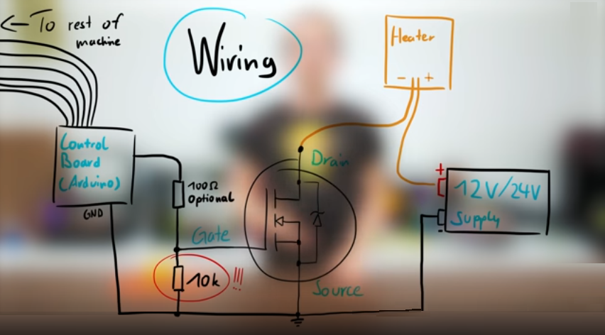
La resistencia de 10KΩ es muy importante utilizarla entre la patilla de Gate y Source, para evitar que el Mosfet actue como una resistencia y se queme.
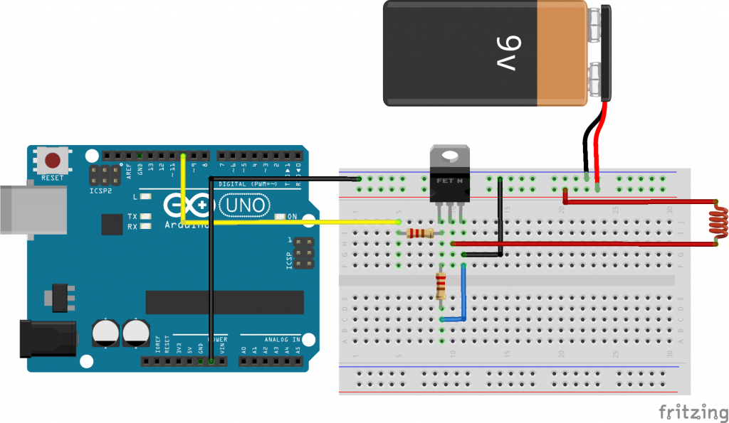
Siguiendo el esquema anterior podemos montar en una placa de prototipado nuestro modelo de funcionamiento.
Para entender este circuito,no está de más decir que la placa no puede alimentar una resistencia para calentarla a unos 200 grados. Es por ello, que requeriremos una fuente de alimentación externa que está representada con una pila de 9V, pero podemos conectar un voltaje mayor siempre que el MOSFET pueda aguantarlo.
Para que este elemento de control funcione, debemos conectarlo correctamente a sus 3 patillas (DRAIN, GATE, SOURCE) y para entenderlo de una manera simple; lo que hacemos es activar la circulación de corriente entre Drain y Source a través de la patilla Gate conectada al Arduino.
Como si de la llave de una tubería se tratara, nuestra placa se encargará de abrirla o cerrarla de forma programada y así proporcionar potencia a nuestro calentador.
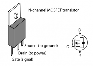
A todo esto, también hay que tener cuidado con el tipo de transistor MOSFET que vamos a conectar, ya que no aguantan todos la misma potencia. Para este ejemplo utilizaremos un MOSFET IRLZ44N.
En un primer ejercicio vamos a controlar la activación de nuestra resistencia por serie y definir los grados a los que queremos que se caliente. Para ello usaremos el método Serial.readInt() que ya conocemos de otros ejercicios.
#include <Servo.h>
int val = 0;

Servo heater ;

void setup() {
  Serial.begin(9600);
  heater.attach(10);
  pinMode(13,OUTPUT);
}

void loop() {
   if(Serial.available() > 0)
   {
      val = Serial.parseInt();
      Serial.println(val);
      if(val != 0)
      {
        heater.write(val);
        digitalWrite(13,HIGH);
      }else{
        heater.write(0);
        digitalWrite(13,LOW);
      }
   }
}
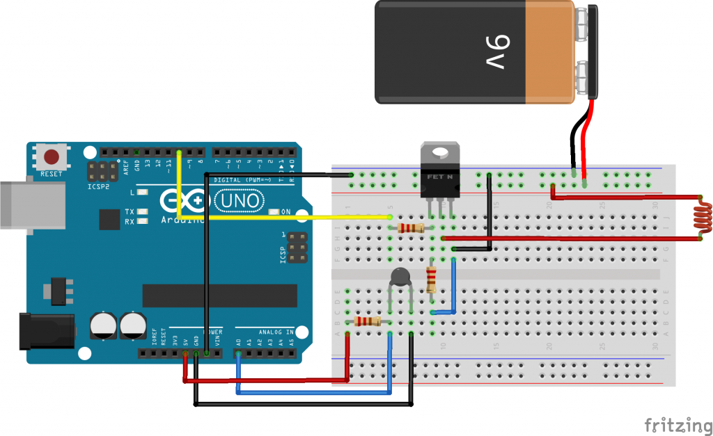
Cuando ya hayamos ejecutado este ejercicio, es momento de aplicar un control ya que no hemos incluido el sensor de temperatura ni la librería de control PID. Para ello conectamos el sensor NTC tal y como habiamos realizado en una lección anterior y unirlo junto a nuestra resistencia controlada con MOSFET.
Para ejecutar esta librería, habremos de atender a 3 variables. SetPoint, Input y Output.
- SetPoint –> Es el valor objetivo que queremos obtener con el controlador. En nuestro caso será la temperatura que queremos que nos proporcione nuestra resistencia.
- Input –> Es la variable que controla y alimenta la resistencia. Será la temperatura computada en cada iteración del bucle de control.
- Output –> Es la variable que nos proporciona la salida de este control. Es decir, el valor obtenido por el sensor.
Además de estas 3 señales, tenemos también 3 parámetros de control. Kp, Ki y Kd; que son parámetros de control en la señal proporcional, integral y derivativa.
Estos parámetros deberemos de estudiarlos para que nuestro sistema sea estable o tenga un respuesta más o menos rápida. Por ahora aplicaremos el siguiente ejercicio con unos valores que iremos ajustando poco a poco.
#define INTERRUPTION 3

volatile int temp = 0;

double Setpoint, Input, Output;
const int sampleRate = 1;

#define  Kp 22.2
#define  Ki 1.08
#define  Kd 114

PID ControlPID(&Input, &Output, &Setpoint, Kp, Ki, Kd, DIRECT);

//Temporal Variables
const long SerialPing =500;
unsigned long now;
unsigned long lastMessage=0;

bool SerialDebug = false;
bool SerialProcessing = false;

// which analog pin to connect
#define THERMISTORPIN A0
// resistance at 25 degrees C
#define THERMISTORNOMINAL 100000
// temp. for nominal resistance (almost always 25 C)
#define TEMPERATURENOMINAL 25
// how many samples to take and average, more takes longer
// but is more 'smooth'
#define NUMSAMPLES 5
// The beta coefficient of the thermistor (usually 3000-4000)
#define BCOEFFICIENT 4066
// the value of the 'other' resistor
#define SERIESRESISTOR 22000

int val =0;

//Temp Steinhart
byte steinhart;

int samples[NUMSAMPLES];

void setup(void) {
  Serial.begin(9600);
  pinMode(10,OUTPUT);
  pinMode(13,OUTPUT);

  ControlPID.SetMode(AUTOMATIC);
  ControlPID.SetSampleTime(sampleRate);

  //InitializeSetPoint
  //Setpoint to 120 degrees
  Setpoint = 120;
  Input=0;
  Output=0;

  analogReference(EXTERNAL);
  Serial.println("Temperature PID ");
  delay(4000);

}

void loop(void) {

    uint8_t i;
    float average;

    if(Serial.available() > 0) //Detecta si hay alguna entrada por serial
   {
      val = Serial.parseInt();
      Serial.println(val);
      if(val != 0)
      {
        analogWrite(10,val);
        digitalWrite(13,HIGH);
      }else{
        analogWrite(10,val);
        digitalWrite(13,LOW);
      }
   }

    Input = temp;

    ControlPID.Compute();

    now = millis();

    if((now-lastMessage > SerialPing) && SerialDebug){
      Serial.print("SetPoint= ");
      Serial.println(Setpoint);
      Serial.print("Input= ");
      Serial.println(Input);
      Serial.print("Output= ");
      Serial.println(Output);
      Serial.print("Temp= ");
      Serial.println(temp);
      Serial.println();
    }

    // take N samples in a row, with a slight delay
    for (i=0; i< NUMSAMPLES; i++) {
     samples[i] = analogRead(THERMISTORPIN);
     delay(10);
    }

    // average all the samples out
    average = 0;
    for (i=0; i< NUMSAMPLES; i++) {
       average += samples[i];
    }
    average /= NUMSAMPLES; // convert the value to resistance
    average = 1023 / average - 1;
    average = SERIESRESISTOR / average;
    float steinhart; steinhart = average / THERMISTORNOMINAL; // (R/Ro)
    steinhart = log(steinhart); // ln(R/Ro)
    steinhart /= BCOEFFICIENT; // 1/B * ln(R/Ro)
    steinhart += 1.0 / (TEMPERATURENOMINAL + 273.15); // + (1/To)
    steinhart = 1.0 / steinhart; // Invert
    steinhart -= 273.15; // convert to C
    if(SerialProcessing){
       Serial.write( 0xff );
       Serial.write( ((int)steinhart >> 8) & 0xff );
       Serial.write( (int)steinhart & 0xff );
    }else{
      Serial.print("Temperature ");
      Serial.print(steinhart);
      Serial.println(" *C");
    }

    delay(1000);

}
Se puede activar el modo de gráfica con Processing para poder ver la evolución de la temperatura. Aunque también se puede activar el Serial Plotter de Arduino.
import processing.serial.*;
import de.bezier.guido.*;


Serial port;  // Create object from Serial class
int val_T, val_V;      // Data received from the serial port
int[] values_V;
int[] values_T;
float zoom;

void setup()
{
  size(680, 480);
  // make the manager

  Interactive.make( this );

  // create a slider

  //slider = new Slider( 2, 2, width-4, 16 );
  // Open the port that the board is connected to and use the same speed (9600 bps)
  port = new Serial(this, Serial.list()[0], 9600);
  values_T = new int[width];
  values_V = new int[width];
  zoom = 1.0f;
  smooth();
}

int getY(int val) {
  println(val);
  return (int)(height - val / 400.0f * (height - 1))-20;
}

int getValue_T() {
  int value = -1;
  while (port.available() >= 3) {
    if (port.read() == 0xff) {
      value = (port.read() << 8) | (port.read());
    }
  }
  return value;
}

int getValue_V() {
   int value = -1;
   while (port.available() >= 3) {
    if (port.read() == 0xcc) {
      value = (port.read() << 8) | (port.read());
    }
  }
  return value;
}

void pushValue_T(int value) {
  for (int i=0; i<width-1; i++)
    values_T[i] = values_T[i+1];
  values_T[width-1] = value;
}

void pushValue_V(int value) {
  for (int i=0; i<width-1; i++)
    values_V[i] = values_V[i+1];
  values_V[width-1] = value;
}

void drawLines_T() {
  stroke(255);

  int displayWidth = (int) (width / zoom);

  int k = values_T.length - displayWidth;

  int x0 = 0;
  int y0 = getY(values_T[k]);
  for (int i=1; i<displayWidth; i++) {
    k++;
    int x1 = (int) (i * (width-1) / (displayWidth-1));
    int y1 = getY(values_T[k]);
    line(x0, y0, x1, y1);
    x0 = x1;
    y0 = y1;
  }
}

void drawLines_V() {
  stroke(0,255,0);

  int displayWidth = (int) (width / zoom);

  int k = values_V.length - displayWidth;

  int x0 = 0;
  int y0 = getY(values_V[k]);
  for (int i=1; i<displayWidth; i++) {
    k++;
    int x1 = (int) (i * (width-1) / (displayWidth-1));
    int y1 = getY(values_V[k]);
    line(x0, y0, x1, y1);
    x0 = x1;
    y0 = y1;
  }
}

void drawGrid() {
  stroke(255, 0, 0);
  line(0, height/2, width, height/2);
}

void keyReleased() {
  switch (key) {
    case '+':
      zoom *= 2.0f;
      println(zoom);
      if ( (int) (width / zoom) <= 1 )
        zoom /= 2.0f;
      break;
    case '-':
      zoom /= 2.0f;
      if (zoom < 1.0f)
        zoom *= 2.0f;
      break;
  }
}

void draw()
{
  background(0);
  drawGrid();
  val_T = getValue_T();
  if (val_T != -1) {
    pushValue_T(val_T);
  }
  drawLines_T();

  val_V = getValue_T();
  if (val_V != -1) {
    pushValue_T(val_V);
  }
  drawLines_V();
}
One comment